Today, at HotChips, MS detailed the Xbox Series X architecture, including the CPU and GPU technologies driving the next-gen console. In this post, the primary focus will be the GPU architecture which is based on AMD’s RDNA 2 along with the various hardware and software optimizations implemented on the side.

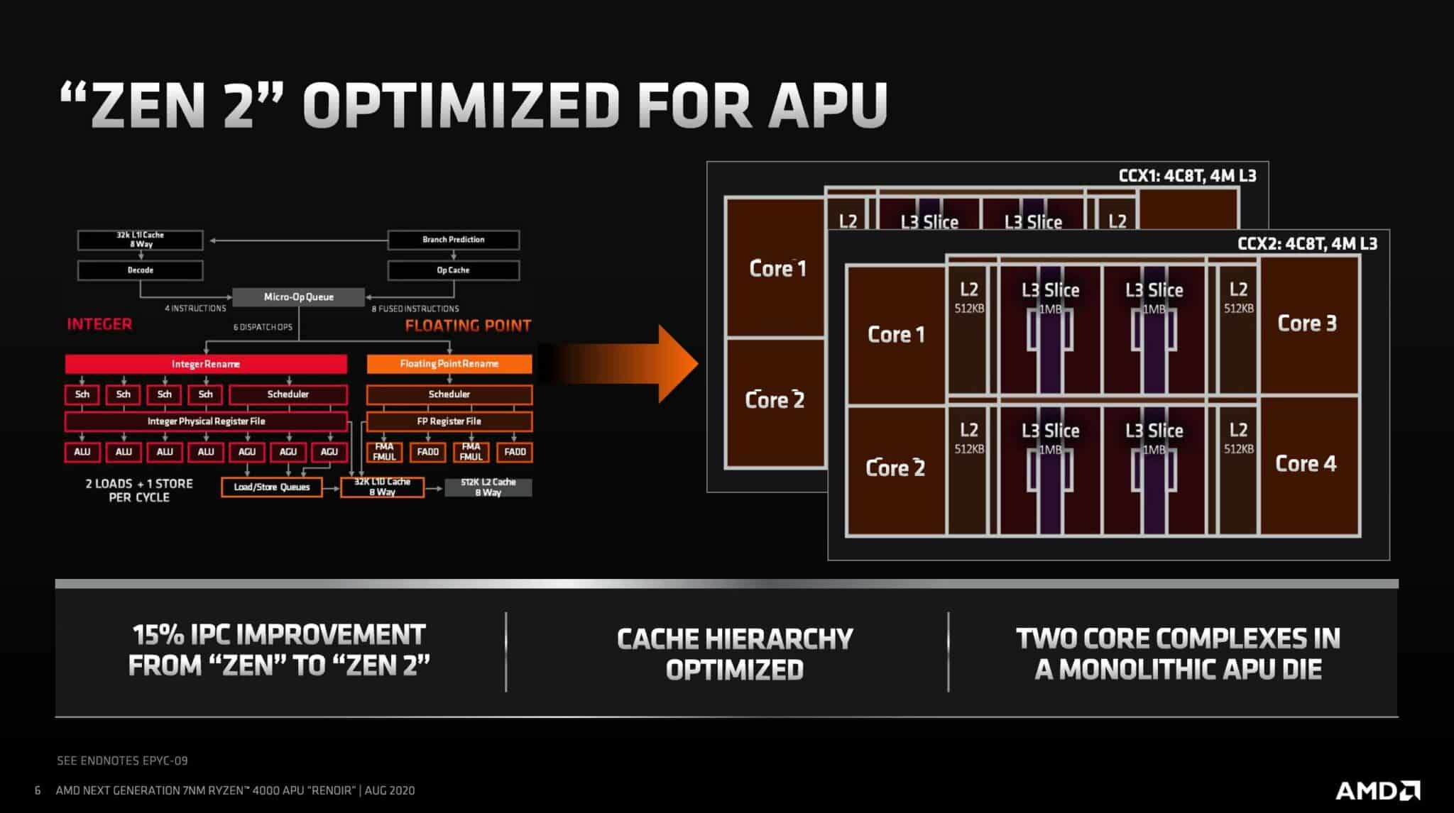
The Xbox Series X CPU is Identical to Mobile Ryzen 4000 APUs (Renoir)
For starters, let’s have a look at the CPU. There are eight Zen 2 CPUs powering the Xbox Series X with a clock speed of 3.8GHz without SMT and 3.6GHz with it. Have a look at the cache architecture: It’s identical to that on the Renoir APUs. The L3 cache is much smaller, more specifically, there is no GameCache which is essentially a fancy term for the fat L3 cache present on all desktop Ryzen 3000 CPUs.
The reason why it’s called GameCache is that it significantly improves gaming performance. The lack of it on the XSX means that the performance will be somewhat lower than the Zen 2 desktop CPUs. To get an idea of how much it actually impacts performance, have a look at this post comparing the Zen 2 CPUs and APUs, where the latter lacks GameCache:
At the same time though, unlike the desktop Zen 2 parts, the CPU and GPU on the Xbox Series X are based on TSMC’s 7nm “enhanced” node. While this isn’t the 7nm+ node or the 7nm EUV node, it’s possibly (not confirmed) the same process that the upcoming Zen 3 based Ryzen 4000 and Epyc Milan CPUs will use. Either that or they are similar to the 7nm “enhanced” transistors powering the Ryzen 3000 XT CPUs. AMD did say that the chips weren’t using the same transistors as the vanilla Matisse parts. Either way, there’s a bit of ambiguity over the process node.
GPU: 1.5 or RDNA 2?
Update: I spoke to AMD and turns out that the GPU is the full-fledged RDNA 2 (The PS5 GPU isn’t confirmed to be based on the same as of now) and as such you can expect the same ray-tracing engine for the Navi 2x GPUs. As for the node, they refused to comment on it.
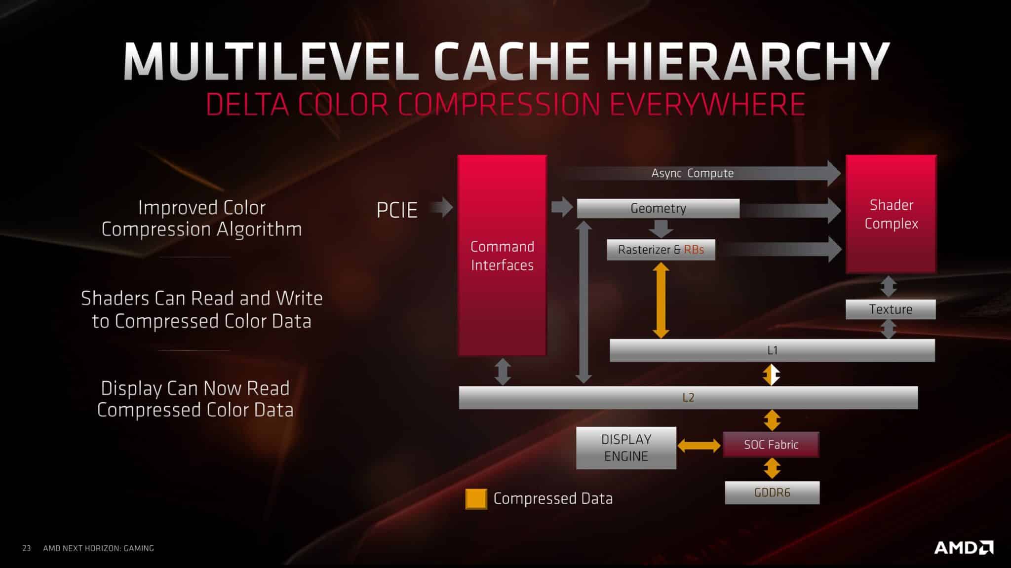
Moving to the GPU block, the architecture itself appears quite similar to RDNA 1 on the outside (you can read about that here). There are 26 DCUs or 52 Compute Units, with 5MB of shared L3 cache (RDNA 1 has 4MB), with each Shader Array of 7 DCUs sharing the L1 cache (with RDNA 1, it was 5 DCUs). Finally, the L0 cache is exclusive to the four SIMDs in a Dual-Compute Unit.
Other than the L2 cache, the primary change at a higher-level is the reduction of Raster Units and the absence of RBs. Like RDNA 1, there’s a unified Geometry Engine and a dual-lane command processor (one for compute, one for graphics). The Render backends seem to be missing from the diagram. I think this is a mistake or they simply decided to omit it.they’re entirely absent from the GPU. It’s possible that the primitive shaders will be taking over their duties due to their programmable nature
There are a bunch of internal tweaks to the Dual-Compute Units (Work Group Processor). The most notable is the inclusion of ray-acceleration hardware: One per SIMD or four per DCU. As per MS, each Compute Unit can do four texture or Ray ops per clock or eight per DCU. That means 208 Ray-tracing operations per clock for the entire GPU. Interestingly, the texture units and ray-acceleration structures share resources between them which means that the effective ray-tracing capabilities will be lower than 208.
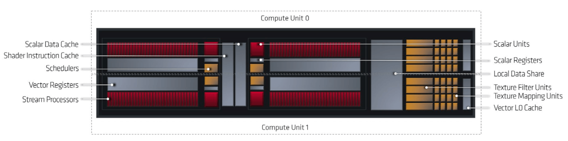
The scalar and vector throughput per DCU appears similar to RDNA, with 32 scalar and 32 FP32 (FMAD) per SIMD or 128 for the four CUs/eight SIMDs in a DCU. One thing I’m curious about here is that in Navi 10, the scalar units are used primarily for control flow and address calculation while the actual graphics processing is done by the vectors. The same applies here as well, meaning there is no asynchronous INT and FP support like NVIDIA’s Turing. Otherwise, there must have been some mention of INT32 or similar workloads
Now, on the pipeline optimizations. We’re basically looking at the same optimizations as with DirectX 12 on PC games. You can read the in-depth post here:
- What is the Difference Between DirectX 11 vs DirectX 12
I’ll be simply summing them up here. The primary technologies are mesh shaders, texture sampler feedback and variable rate shading:
Mesh Shaders: The mesh shader performs the same task as the domain and geometry shaders but internally it uses a multi-threaded instead of a single-threaded model. The task shader works similarly. The major difference here is that while the input of the hull shader was patches and the output of the tessellated object, the task shader’s input and output are user-defined.
In the above scene, there are thousands of objects that need to be rendered. In the traditional model, each of them would require a unique draw call from the CPU. However, with the task shader, a list of objects using a single draw call is sent. The task shader then processes this list in parallel and assigns work to the mesh shader (which also works synchronously) after which the scene is sent to the rasterizer for 3D to 2D conversion.
This approach helps reduce the number of CPU draw calls per scene significantly, thereby increasing the level of detail.
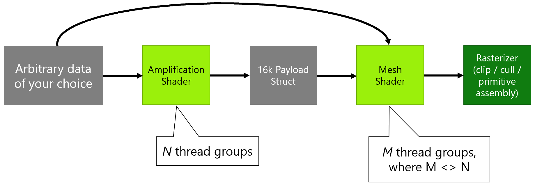
Mesh shaders also facilitate the culling of unused triangles. This is done using the amplification shader. It runs prior to the mesh shader and determines the number of mesh shader thread groups needed. They test the various meshlets for possible intersections and screen visibility and then carry out the required culling. Geometry culling at this early rendering stage significantly improves performance.
Texture Sampler Feedback: TSF is something MS is really stressing on. In simple words, it keeps a track of the textures (MIP Maps) that are displayed in the game and which are not. Consequently, the unused ones are evicted from the memory, resulting in a net benefit of 2.5x to the overall VRAM usage. In the above image, you can see, that on the right (without TSF), the entire texture resources for the globe are loaded into the memory. With TSF on the left, only the part that’s actually visible on the screen is kept while the unused bits are removed, thereby saving valuable memory.
This can be done across frames as well (temporally). In a relatively static image, objects in the distance can reuse shading over multiple frames, for example, over each two to four frames and even more. The graphics performance saved can be used to increase the quality of nearby objects or places that have a more apparent impact on quality.
Variable Rate shading: Variable Rate Shading shading allows the GPU to focus on areas of the screen that are more “visible” and affected per frame. In a shooter, this would be the space around the cross-hair. In contrast, the region around the border of the screen is mostly out of focus and can be ignored (to some degree).
It allows the developers to focus more on the areas that actually affect the apparent visual quality (the center of the frame in most cases) while reducing the shading in the peripheries.
VRS is of two types: Content Adaptive Shading and Motion Adaptive Shading:
CAS allows individual shading of each of the 16×16 screen tiles (tiled rendering), allowing the GPU to increase the shading rate in regions that stand out while reducing them in the rest.
Motion adaptive shading is as it sounds. It increases the shading rate of objects that are in motion (changing every frame) while reducing that of relatively static objects. In the case of a racing game, the car will get increased shading while the sky and off-road regions will be given reduced priority.
A note on the ray-tracing capabilities of the Xbox Series X:
MS figures on the ray-tracing performance of the Xbox Series X are rather vague. The GPU section mentions ray-ops of up to 208 per cycle. However, the above slide says 380G/s (Gigarays?) ray-box peak or 95G/sec ray-triangle peak.
DF said that the XSX can perform 380 billion intersections per second, but this slide muddles it all. My guess is that the latter refers to the actual number of ray-triangle intersections which is an important part of the ray-tracing process while the former is the peak rays cast per cycle. However, none of them actually represent the actual ray-tracing performance and the ray-ops figure of 208 is the closest one to it. For reference, the RTX 2080 Ti has a rating of 8 Gigarays per second. Note that while MS provides the peak value for G/sec without any bottlenecks, NVIDIA states the typical performance.
The actual implementation is identical. The BVH is offloaded to the dedicated hardware while the primary shaders continue to work as normal.